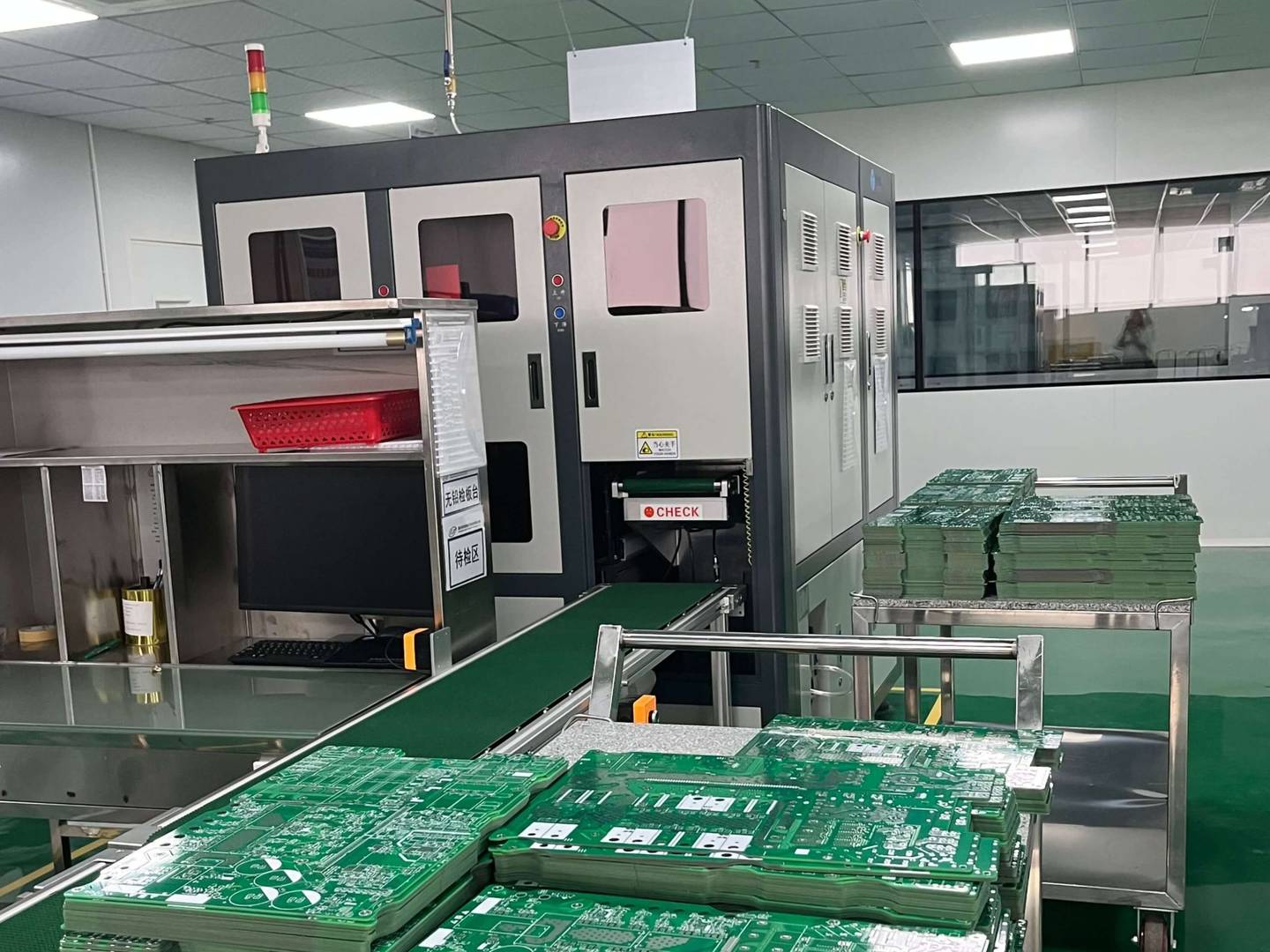
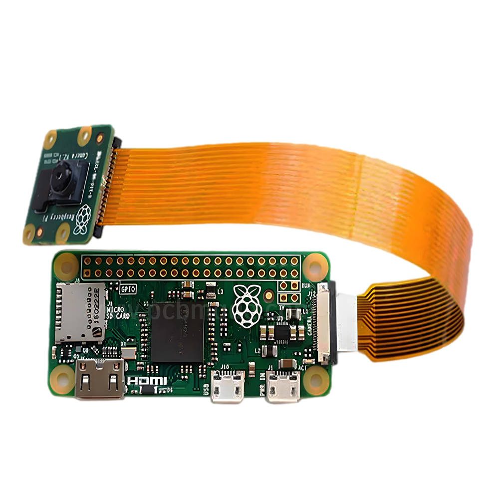
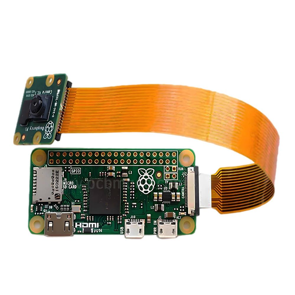
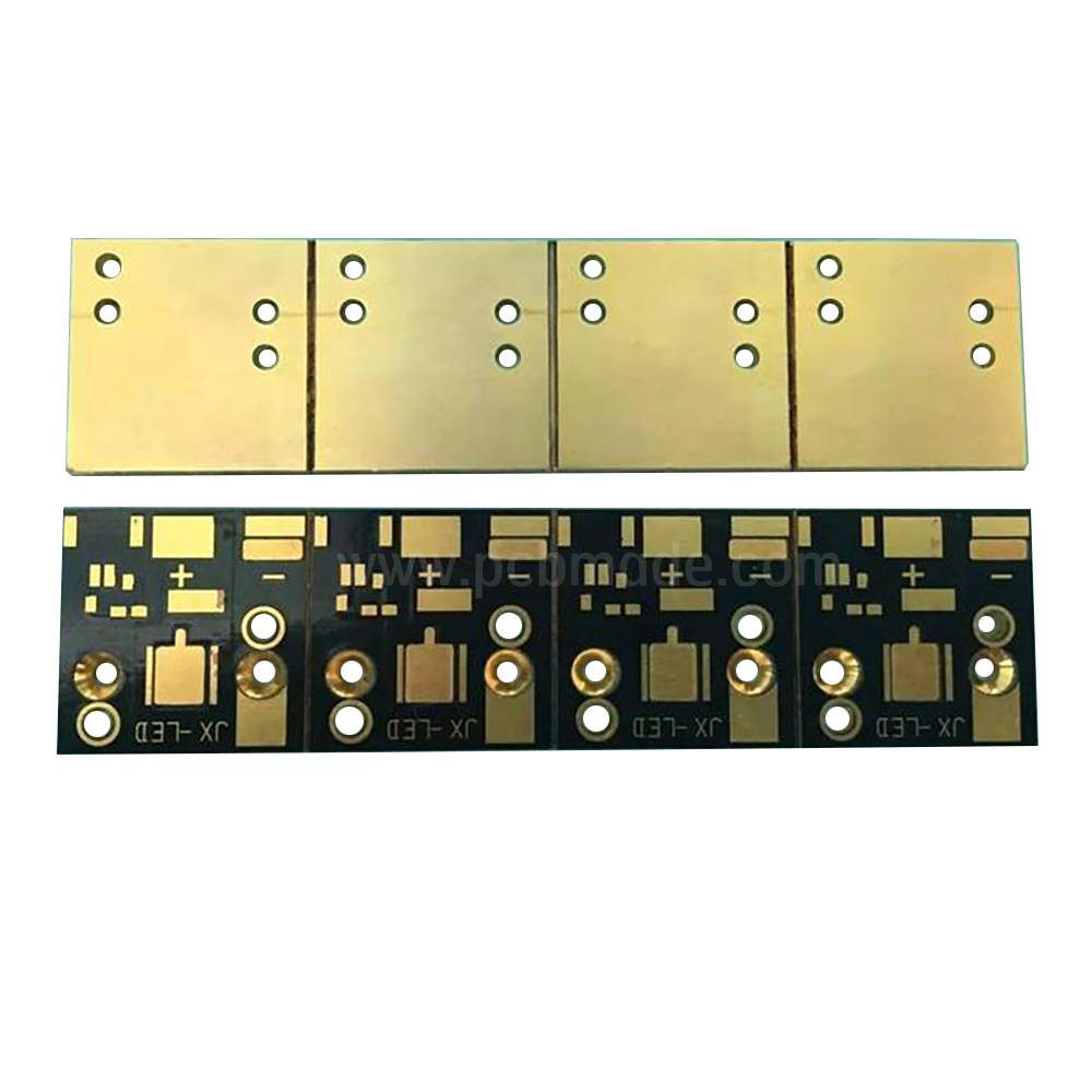
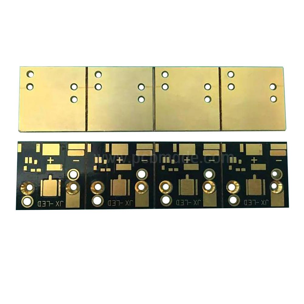
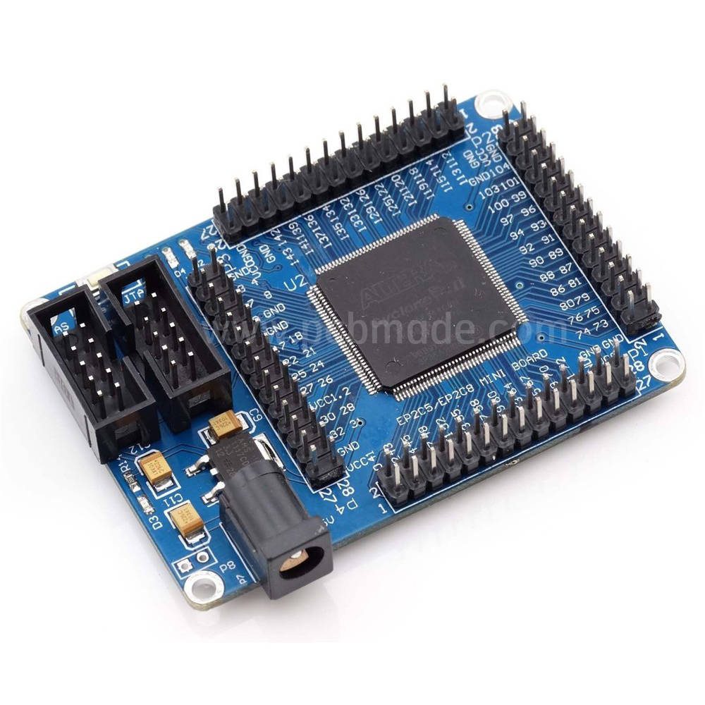
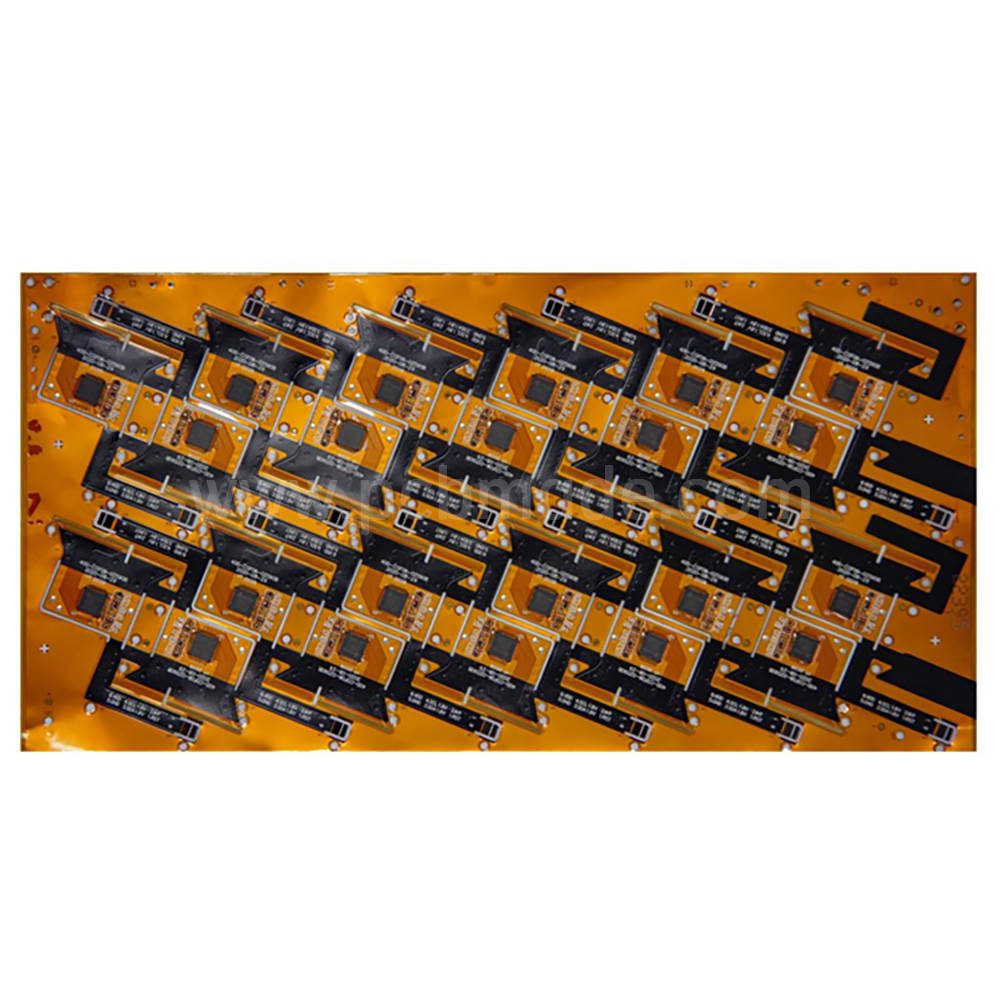
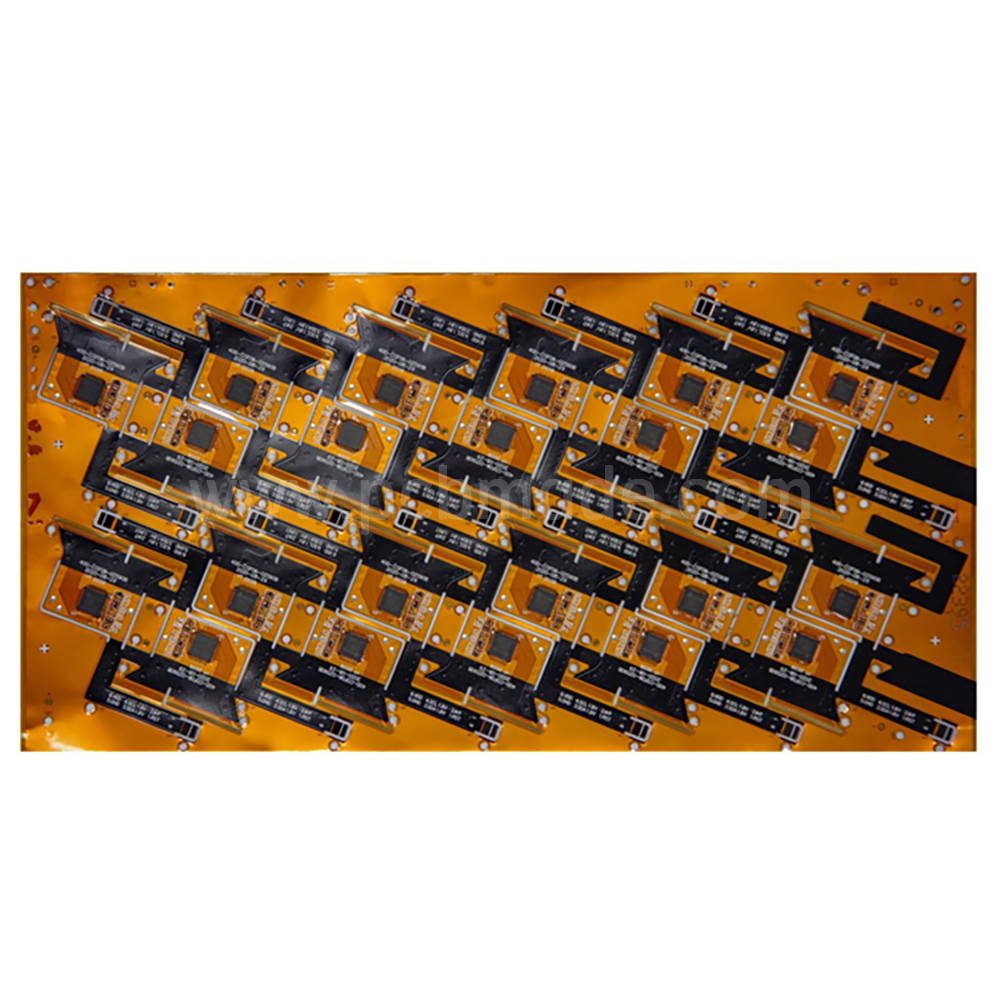
A PFC PCBA (Power Factor Correction Printed Circuit Board Assembly) is a critical component in modern power electronics, designed to improve energy efficiency and reduce harmonic distortion in AC/DC conversion systems. It integrates advanced topologies like Boost PFC or Flyback PFC with GaN/SiC MOSFETs to achieve efficiencies exceeding 95%, complying with global standards such as RoHS and ISO 26262 for automotive safety . Key features include configurable input ranges (90–264V AC), planar transformers for compact designs, and ENIG-finished FR4 PCBs to ensure durability in harsh environments . These assemblies support USB PD 3.1 and QC4+ fast-charging protocols in adapters, while enabling high-power applications like EV charging stations and AI servers through multi-layer thermal management (e.g., aluminum heatsinks and thermal interface materials) . Rigorous validation via AOI and FCT guarantees reliability, making PFC PCBAs essential for meeting global energy regulations and Industry 4.0 demands.


